Raytheon Autonomous Drone Project Semester 1
This school year I am working on my Senior Design project, a two-semester long course in the UTD engineering program. At the beginning of the fall semester, students apply to 5 projects that interest them. Similar to applying for jobs they answer questions like "why do you think you would be a good fit for this project?". What project the student ends up assigned to depends on how relevant their experience is and how they answer the questionnaire. All of the projects have them building out a project/product, then showing it off at the end of the semester during the UTDesign EXPO (An engineering fair for senior design projects). Most projects are sponsored by a company and given a corporate advisor to help guide the students.
The project I chose to work on is a Raytheon-sponsored autonomous drone project which would compete with other Texas Universities Raytheon-sponsored teams (UT, UTA, UTEP, SMU, A&M). The premise described to us was simple, we get a budget ($5k) and a set of challenges the drone must complete. At the end of the spring semester (April), all of the sponsored teams would get together and see whose drone completes the challenges the best. The criteria the drones are judged upon are speed in completing the challenge and accuracy during the challenge. The challenges are as follow:
- Challenge 1 – Does your drone work? (Autonomous Flight and Landing)
- Lift-off on the Zero yard line to a preset altitude, move and land on the 30-yard line.
- Challenge 2 – Find your school logo (Autonomous Flight and Landing)
- Lift-off at the Zero yard line, search for a school logo, then land on the school logo
- Challenge 3 – Obstacle Course (Autonomous Avoidance)
- Lift-off at the Zero yard line and navigate through an obstacle course of pool noodles
- Challenge 4 - Indoor collision avoidance – No GPS (Autonomous Avoidance)
- Same as Showcase 3 but with No GPS and indoors
- Challenge 5 - Surprise Mystery Challenge!
- Details would be given a week before the competition
Note: All challenges have altitude limits and take place on a football field (Except Challenge 4).
Some other requirements for the project are:
- The use of JIRA and Agile methodologies
- Github
- Weekly Sponsor Meetings
- RTK GPS Capabilities
- Teamwork!
Research:
This year is the second annual competition, meaning last year UTD competed against UTA and UTEP in challenges 1-3. UTA's drone was the only one able to complete all 3 challenges. UTD's drone only completed Challenges 1 & 2, and they were able to use a homing beacon in their logo during Challenge 2 making it significantly easier.
We decided to first pick up where last year's team left off, which would be a 60-page report and a bunch of drone pieces in a box. Last year's drone had lost connection during a drag race after the competition and turned itself back into its base components by smashing into the ground, meaning we didn't have a working drone.
The main makeup of an autonomous drone consists of these components:
- Flight Controller - The brain of the whole operation, controls all motor output, ground control communication, flight data, autonomous flying, and more.
- GPS - Used by the Flight Controller to keep precise location when doing autonomous missions.
- ESC's & Motors - The ESC receives power from the PDB and signals from the flight controllers to spin the motors. Typically each Motor has its own ESC.
- Power Distribution Board (PDB) - Controls power input from batteries and output to ESCs which go to Motors, sometimes also handles PWM signals from the flight controller to ESCs.
- Radio Receiver - Connects the radio to the flight controller to control the drone manually. Also functions as a failsafe so pilots can take control during autonomous flights.
- Telemetry Transmitter - Connects to the Ground Control Station (GCS) to the flight controller to transmit various flight data and control autonomous drone functions.
- Companion Computer (Optional) - An onboard computer that connects to the flight controller to run custom scripts. Usually communicates to Ardupilot via MAVLink protocol.
- Frame - Everything the drone components mount to, typically a Carbon fiber premade frame but sometimes custom 3D printed.
- Battery - Powers the drone and all of its components, typically LiPo. Size and capacity vary per drone.
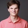
Thankfully we had an experienced drone builder on our team, William Greenfield, who spearheaded our initial research into what we would want to build our drone with. Out of our parts bin, we found enough components to build a prototype quadrocopter.
Our prototype quadrocopter consists of these components, nearly all of them are from last year's team:
- Flight Controller - Initially a Holybro PX4 2.4.6, but later a Pixhawk 4 (Better internal hardware). Both running Ardupilot, an open-source Autonomous drone firmware.
- GPS - Holybro UBLOX M8P RTK GPS.
- ESC's & Motors - DJI ESC's and EMAX motors from last year's quadcopter.
- Power Distribution Board (PDB) - Pixhawk 4 Power Module. Initially, we did not need this but the Pixhawk 4 Flight controller required it when we switched later.
- Radio Receiver - Frsky XM+. Fantastic range and good transmitter compatibility with our Taranis Q X7
- Telemetry Transmitter - Holybro SiK Telemetry Radio V3
- Companion Computer (Optional) - Raspberry Pi 4 with a better wifi antenna for longer distance
- Frame - Some old quadcopter frame AIAA had lying around we could use instead of last year's 3D printed frame. (Major weight savings)
- Battery - 4S 5000 mAh LiPo
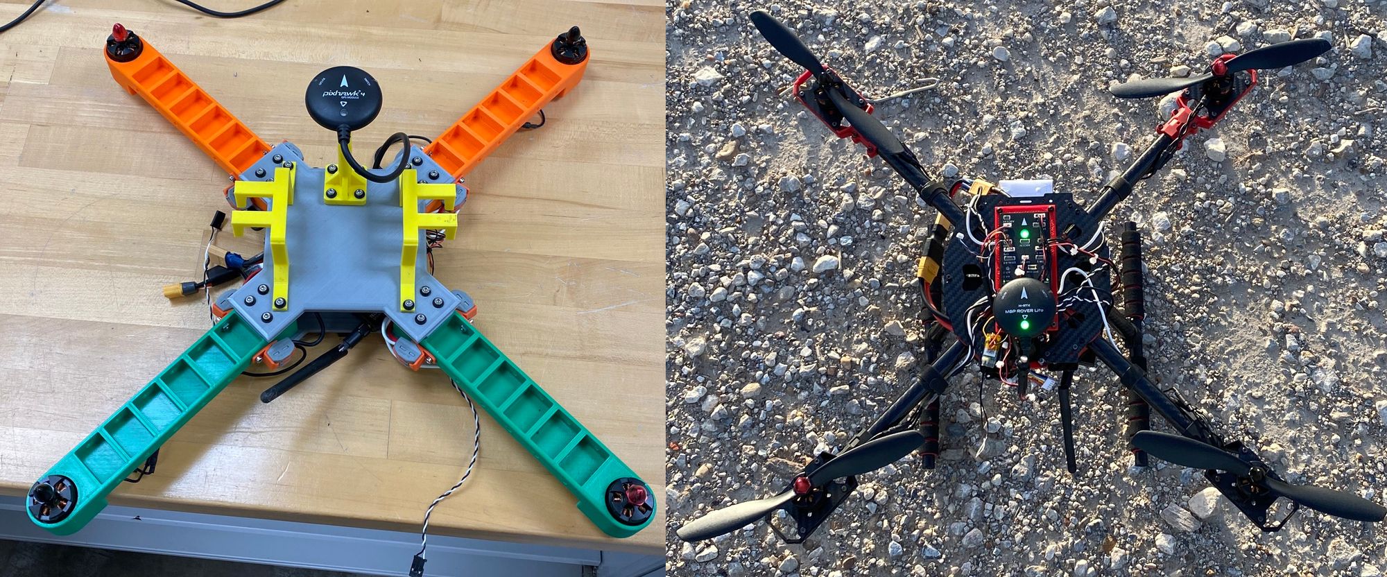
- On-board camera - Raspberry Pi HQ Camera mounted on a custom servo mount I made in Fusion360.
Here is a small mockup of the drone from Fusion360 in <model-viewer> and a photo of the completed prototype quadcopter. We assembled the drone using our own tools, Fusion360 for CAD, Personal & UTDesign Makerspace 3D printers, and spare parts. All orange parts (and the red camera servo system) are designed and printed by us.
While we were building this prototype quadcopter we were also strategizing on how to complete each challenge. We had decided to break up our 13 person team into subteams for each challenge (7 Electrical or Computer Engineers, and 6 Computer Scientists). For now, our subteams were General (Building & Implementing onto quadcopter), Challenge 1 (Simulate & Code), and Challenge 2 (Research).
Here were our big picture approaches at this stage of the project after some hands-on experience with the quadcopter:
- Challenge 1 - Takeoff and land on the 30-yard line
- Our approach is to use Ardupilot's built-in autonomous GPS navigation to complete this challenge. It would not require a companion computer to execute a script, but it would speed up the process of the mission if it had one.
- Challenge 2 - Takeoff, find our logo and land on it
- One member of our team, Noah Parker, has experience using OpenCV and suggested Aruco markers (QR codes cameras can detect easily). We liked this idea and it avoided us having to use Machine Learning entirely, saving us a ton of time. This would require a companion computer to take camera data, process it, then guide the flight controller to land on the marker.
- Challenge 3 - Autonomously navigate an obstacle course
- We had found a LiDAR unit lying around and decided to do some testing with that before deciding our approach. We also considered some kind of stereo camera systems, machine learning, or OpenCV to detect and avoid obstacles. Largely undecided approach until we were further in Challenge 1 and 2.
- Challenge 4 - Challenge 3 but with no GPS and indoors
- This was put off to be done later after work was done in designing the final drone and Challenge 3.
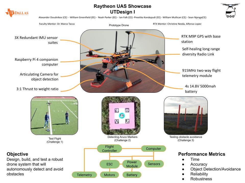
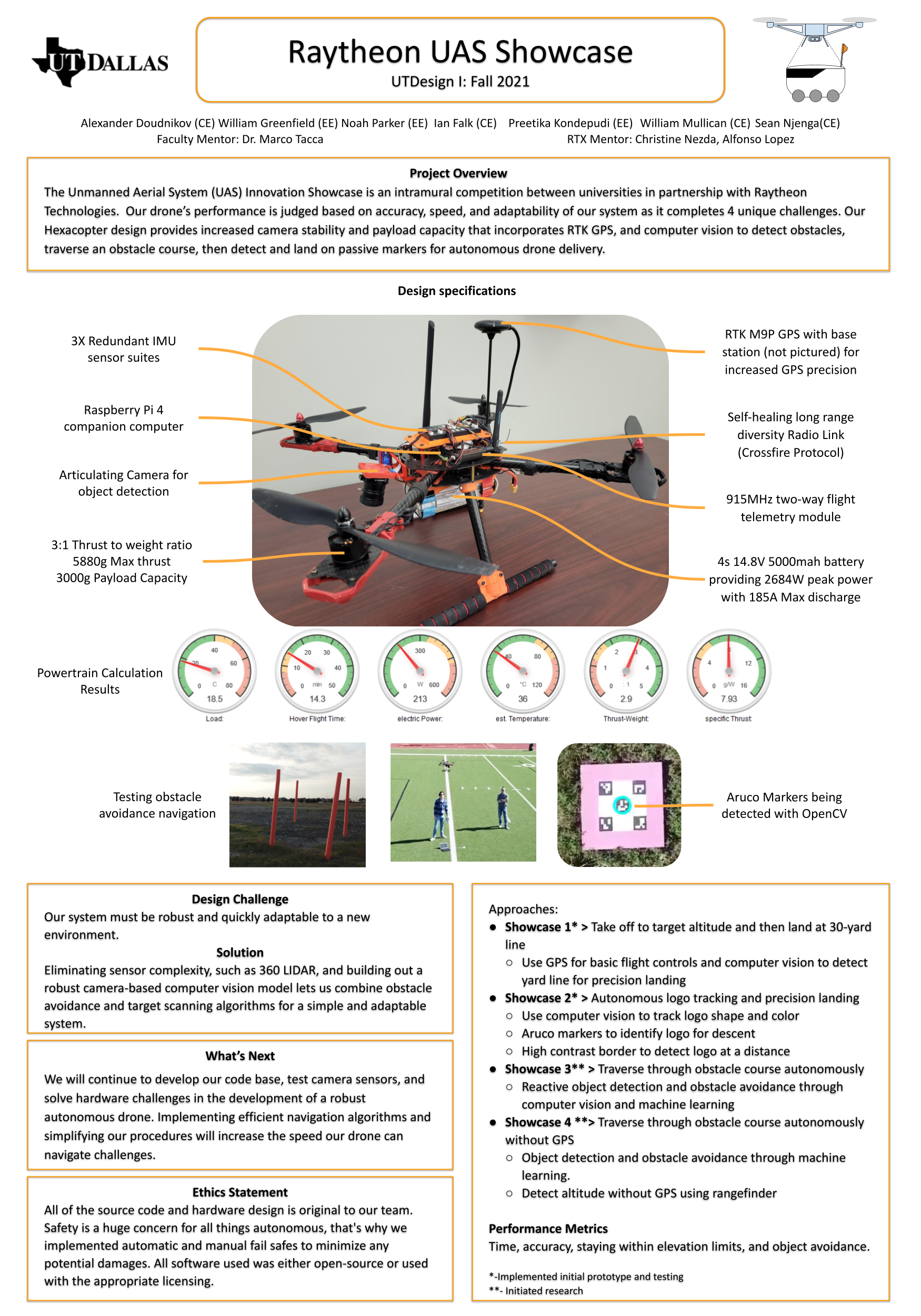
By now it was around early November, we had a rough roadmap of implementing most of the challenges and a few test flights under our belt to figure out what works and what doesn't on the quadcopter. Using this we did a rough specification sheet of our final hexacopter build. At the time we thought it would look something like this:
- Flight Controller - Ardupilot Cube Orange (Triple redundant IMU's and better hardware)
- GPS - Holybro UBLOX F9P RTK GPS (Better antenna and RTK chip)
- Radio Receiver & Telemetry Transmitter - Same as quadcopter
- Companion Computer - Raspberry Pi 4, upgrading to Nvidia Jetson if available or required.
- Frame - DJI F550 Hexacopter frame
- ESC's, Motors, PDB, Battery - To be selected later using our eCalc (Drone powertrain calculator) results, which are heavily dependent on other components' weight.
- On-board camera/sensors - 2x Cameras, 3x Ultrasonic distance sensors, and a 360-degree LiDAR, all for logo detection, distance detection, and obstacle avoidance.
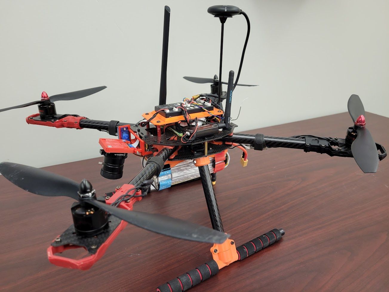
After figuring out the payload weight we'd need to carry, Will did our eCalc to get the best possible performance out of the drone. This is a delicate balance of motor power, hover time, battery size, and many other factors to get the optimal setup. We chose to go for a comfortable 15 minute hover time and a 3:1 weight lift ratio. These are our eCalc results for the hexacopter:
Challenge 1:
To start coding the actual challenges we started using SITL (Software in the Loop) Simulator. This simulator was capable of simulating everything we can do with our Ardupilot flight controller and companion computer, all in a virtual environment.
All of our Challenge 1 code was written in SITL then later tested on the quadcopter. It was done by writing a script in python, utilizing a library called dronekit to communicate with the flight controller (simulated or real) from the companion computer via MAVLink. On the actual prototype quadcopter, we used a Raspberry pi 4 to run our Challenge 1 code while connected to the Pixhawk 4 flight controller.
Challenge 1 SITL code available here (Not public until after the competition) we wrote for Challenge 1 SITL, but to put it simply:
- The companion computer connects to the flight controller via MAVLink.
- Once connected it sets a landing waypoint 30 yards ahead of itself, along with a takeoff waypoint to a preset altitude.
- When ready, it arms the drone and runs the mission to takeoff then land on the 30 Yard line.
- Once landed the mission is complete.
Our initial flight tests were accurate within a yard of the line usually, we ran into an issue early on with our compass not lining up but that was fixed with some calibrations. Later on, we introduced an RTK base station that made the drone more accurate.
Wrapping Up Fall Semester:
After we did our Challenge 1 Demo in early December for our sponsors using our prototype quadcopter, we shifted our focus to building out Challenges 2-4. This meant we needed to finish designing the hexacopter, build it, and also simulate and integrate challenges 2-4 onto it.
Building the hexacopter is simple: we just have to place the orders, wait for the parts to arrive, and mount everything together through the magic of CAD and 3D printing. Simple! Unfortunately, we were impacted by the chip shortage making it difficult to source all of the parts we needed in a timely manner, but all of the parts eventually did show up early next year.
Before the Fall Semester came to an end I began working on simulating Challenge 3/4. SITL is a fantastic drone simulator but we would not be able to simulate sensors like a 360 LiDAR or it detecting obstacles. For this, we turned to use Gazebo, a robotics simulator that only runs on Ubuntu (and requires a graphics card). Gazebo would enable us to simulate the full 3D worlds the SITL drone can fly in. More on this next semester after winter break.
UTDesign Senior Design 1 Fall Expo:
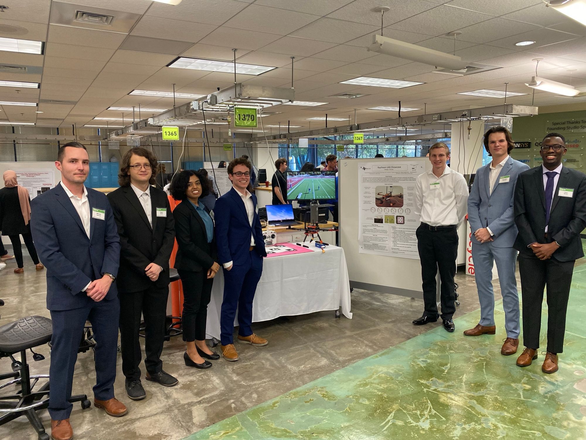
At the end of each semester, UTDesign holds an engineering expo where students can show off the senior design projects they have been working on to engineering industry professionals who judge them. There are two main groups of projects, ECE (Electrical and Computer Engineering) and BMEN (Biomechanical Engineering)/ME (Mechanical Engineering) projects. Our project is a part of the ECE group of projects. There is both first semester (prototype) and second semester (completed) projects being displayed at the expo. We are a first-semester project.
Expo consists of our team giving a short 5-minute presentation over our project, along with a short questions session afterward. Then once all teams have presented we move to the design lab, where projects are on display along with a poster detailing the project. During this time, judges come around and ask questions about our project. Afterward, awards are given out to the teams the judges think did the best on their projects.
Our project won 3rd place in the first semester ECE projects. Below you can see some pictures and a video from EXPO.
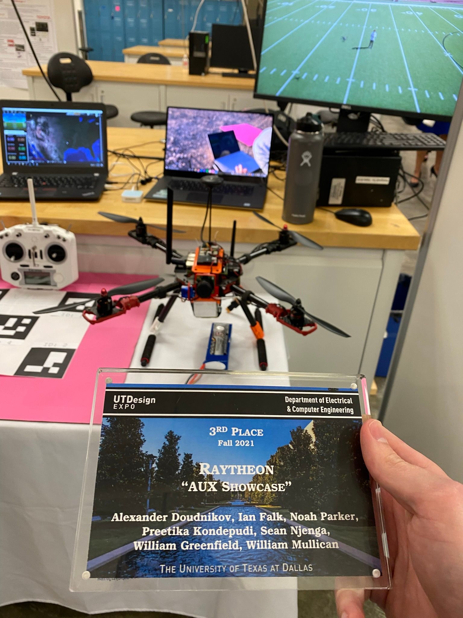
This wraps up the first semester of my work on the UTD Raytheon AUX team.
See next semester's work here: alex.doud.io/raytheon-drone-project-sem-2/